MOSFET H-bridge with very low voltage drop -- far more efficient than L298N
In stock
Motor Drivers
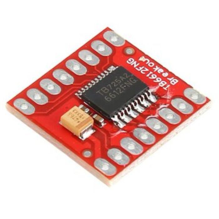
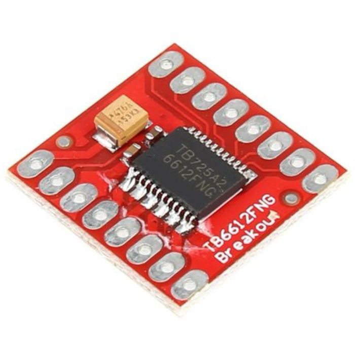
TB6612FNG Dual DC Motor Driver Module
Compact dual-motor MOSFET driver, 1.2A constant (3.2A peak) per channel, efficient L298N replacement.
₹280 + 18% GST
SKU: BOTBIT-MOT-11 · Best for: Efficient, longer-runtime battery-powered robot cars
Overview
About TB6612FNG Dual DC Motor Driver Module.
The TB6612FNG dual DC motor driver is a compact, efficient MOSFET-based board built around Toshiba's TB6612FNG chip, widely recommended as a modern replacement for the aging L298N. Because it uses MOSFETs instead of bipolar transistors, its voltage drop is tiny (well under 0.5V per side versus the L298N's ~2V), so more of your battery voltage reaches the motors and far less energy is wasted as heat.
It is popular in India with makers building efficient robot cars, especially battery-powered ones where the L298N's losses shorten runtime. It drives two DC motors independently (direction plus PWM speed) or one bipolar stepper, delivering 1.2A continuous and 3.2A peak per channel, with built-in thermal shutdown and a standby pin for low-power sleep.
The board is small and breadboard-friendly, needs separate motor (VM) and logic (VCC) supplies, and works with any 2.7-5.5V logic microcontroller including Arduino, ESP32 and Raspberry Pi. Libraries and example sketches (including Sparkfun and Pololu ones) make it easy to drop into existing projects.
Key features
Why it stands out.
Two DC motors independently, or one bipolar stepper
1.2A continuous and 3.2A peak per channel
Separate motor (VM 2.5-13.5V) and logic (VCC 2.7-5.5V) supplies
PWM speed control up to ~100 kHz, plus a standby (STBY) low-power pin
Built-in thermal shutdown and under-voltage lockout protection
Specifications
Selection facts.
| Driver IC | Toshiba TB6612FNG |
|---|---|
| Motor supply voltage (VM) | 2.5 - 13.5V DC |
| Logic supply voltage (VCC) | 2.7 - 5.5V |
| Continuous current per channel | 1.2A |
| Peak current per channel | 3.2A (pulse) |
| Channels | 2 (dual H-bridge) -- two DC motors or one stepper |
| PWM frequency | Up to ~100 kHz |
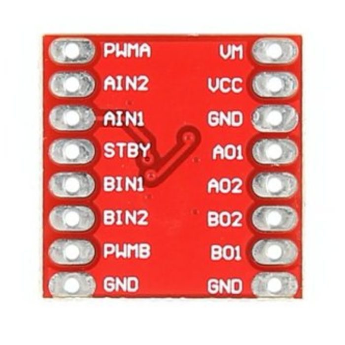
| Control pins | AIN1/AIN2, BIN1/BIN2, PWMA, PWMB, STBY |
| Voltage drop | Very low (MOSFET output stage) vs ~2V for L298N |
| Protection | Thermal shutdown, under-voltage lockout |
Applications
Where it is used.
- Efficient, longer-runtime battery-powered robot cars
- Line-following and maze-solving robots needing precise low-loss speed control
- Compact builds where the bulky L298N will not fit
- Driving a single small bipolar stepper
- ESP32/Arduino projects wanting quiet, cool, efficient dual-motor drive
Buying guide
How to choose.
Buy the TB6612FNG when you want an efficient, compact upgrade over the L298N -- especially for battery robots where runtime and low heat matter. Its low voltage drop means small motors get nearly the full battery voltage. If you need to drive motors above 13.5V or above ~3A, choose a higher-voltage/current driver instead, as the TB6612FNG maxes out at 13.5V motor supply.
Remember it needs two supplies: VM for the motors (2.5-13.5V) and VCC for logic (2.7-5.5V, tie to your microcontroller's 3.3V or 5V). You must also drive the STBY pin high to take the driver out of standby, a common first-time gotcha. Connect all grounds together.
Pair it with an Arduino, ESP32 or Raspberry Pi, two small DC gear motors (or one bipolar stepper), and a suitable battery under 13.5V. Use PWMA/PWMB for speed via analogWrite and the AINx/BINx pins for direction. Sparkfun and Pololu provide ready libraries and wiring examples.
FAQ
Common questions.
How is it better than the L298N?
It uses MOSFETs, so its voltage drop is a fraction of the L298N's ~2V. That means more battery voltage reaches your motors, much less wasted heat, and longer battery life -- all in a far smaller board. The trade-off is a lower 13.5V motor-supply ceiling and 3.2A peak (vs 3A) per channel.
Why won't my motors turn even though wiring looks right?
The most common cause is the STBY (standby) pin being left low. Tie STBY high (to VCC or a GPIO set high) to enable the driver. Also confirm VM has motor power and all grounds are common.
What pins control speed and direction?
Use PWMA/PWMB for speed (analogWrite/PWM) and AIN1/AIN2 (motor A) and BIN1/BIN2 (motor B) for direction. Setting both direction pins the same acts as brake or coast depending on the combination.
What is the maximum motor voltage and current?
Motor supply (VM) is 2.5-13.5V; each channel does 1.2A continuous and 3.2A peak. For higher voltage or current, use a different driver. Logic VCC is separate at 2.7-5.5V.
Can it drive a stepper motor?
Yes, one bipolar (4-wire) stepper using the two channels as the two coils, sequenced by the AIN/BIN pins. For dedicated stepper work with microstepping, use an A4988, DRV8825 or TMC2209 instead.
Is it available in India and what is in the box?
Yes, it is readily available in India. The board ships as a single TB6612FNG breakout, usually with header pins (sometimes unsoldered); motors, battery and microcontroller are separate.
More in Motors & Drivers
Related hardware.
Motor Drivers
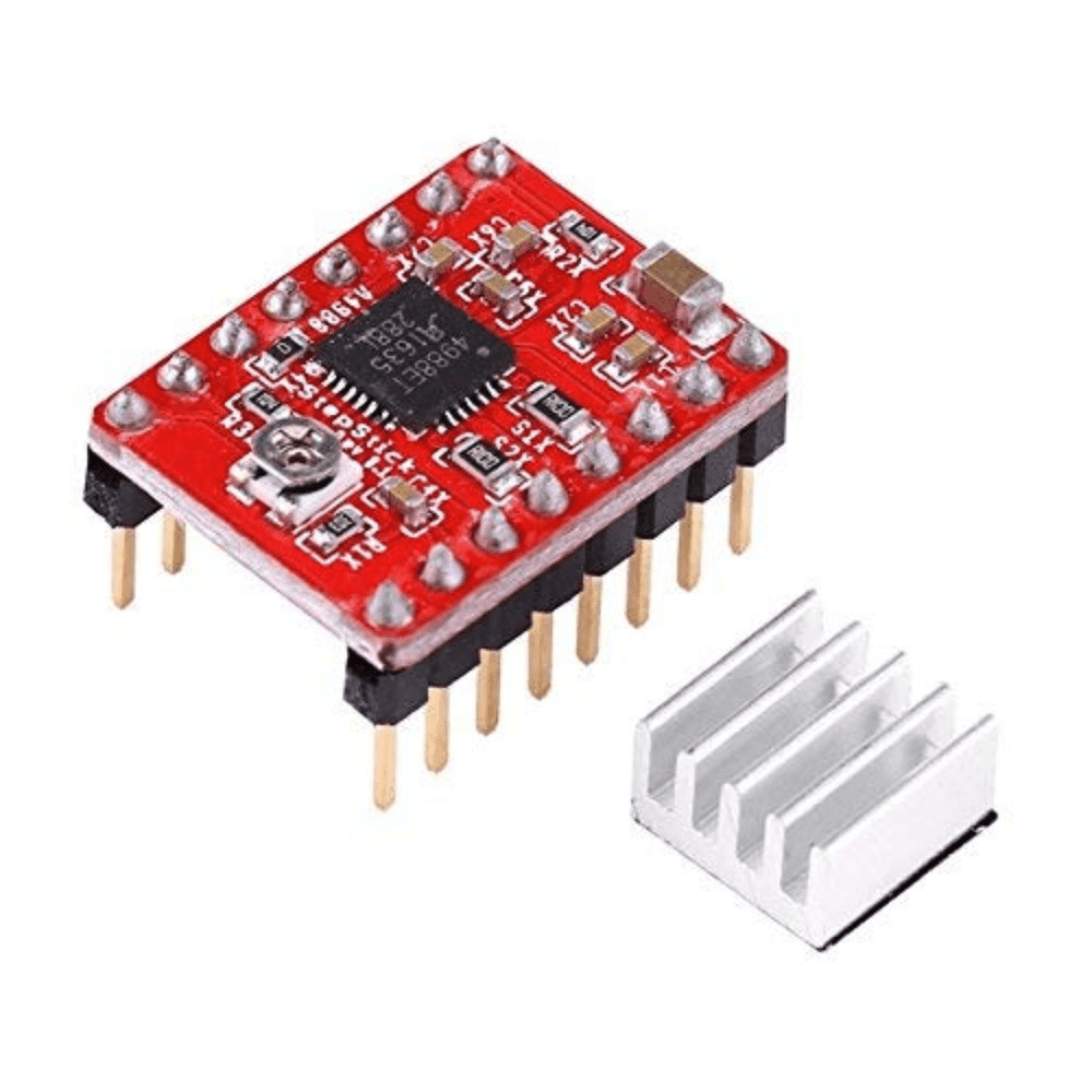
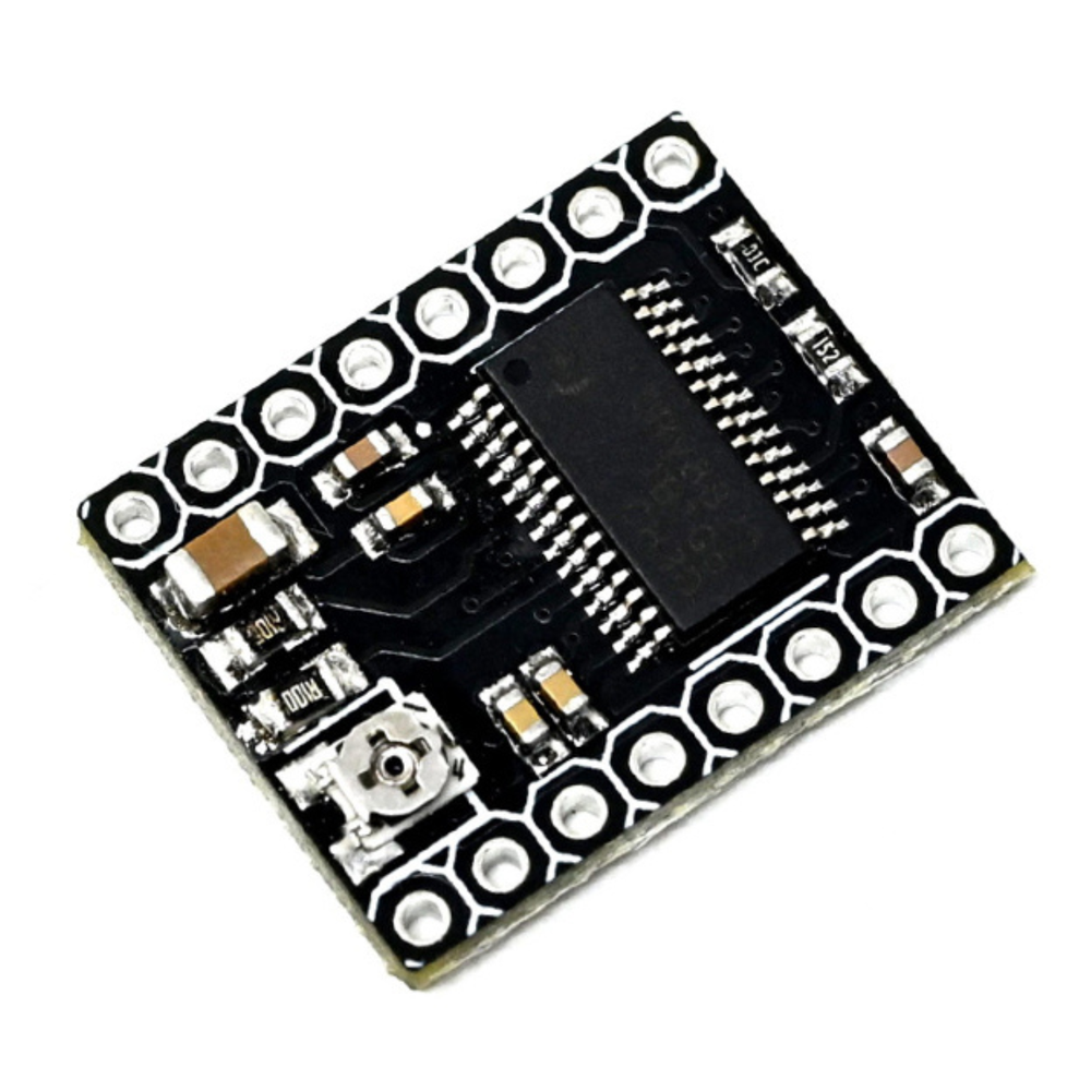
A4988 Stepper Motor Driver Module with Heat Sink
Microstepping bipolar stepper driver (up to 1/16), 8-35V, standard RAMPS/3D-printer StepStick.
₹85 + 18% GST
Motor Drivers
DRV8825 Stepper Motor Driver Module with Heat Sink
Bipolar stepper driver up to 1/32 microstepping, ~2.2A peak, higher-current A4988 alternative.
₹140 + 18% GST
Motor Drivers
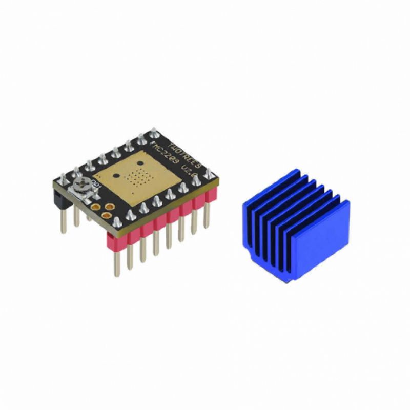
TMC2209 Stepper Motor Driver Module
Silent StealthChop stepper driver up to 1/256 microstep with UART, popular 3D-printer upgrade.
₹320 + 18% GST
Motor Drivers
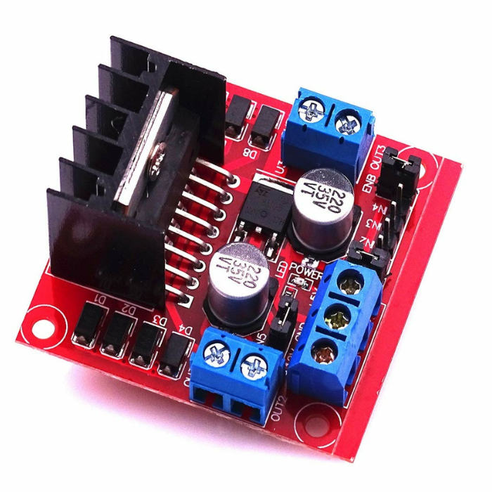
L298N Dual H-Bridge Motor Driver Module
Dual H-bridge driver, 5-35V up to 2A/channel, controls two DC motors or one stepper; widely used module.
₹170 + 18% GST
You may also need
Pairs well with.
Arduino Boards
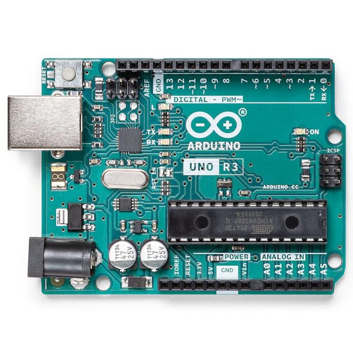
Arduino Uno R3
The classic ATmega328P 8-bit microcontroller board, a popular beginner prototyping platform with 14 digital and 6 analog I/O pins.
₹799 + 18% GST
Breadboards Jumpers
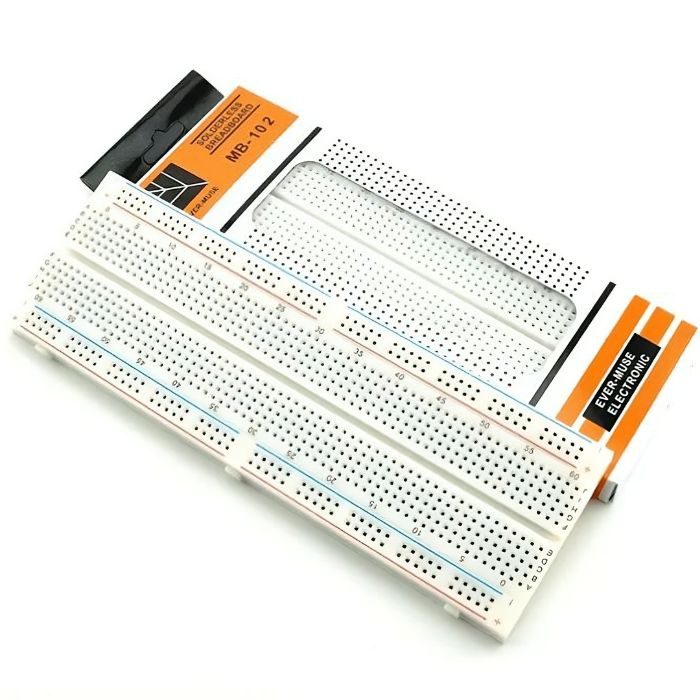
MB102 830 Points Solderless Breadboard
Full-size 830 tie-point solderless prototyping breadboard with power rails, accepts 20-29 AWG wire.
₹90 + 18% GST